
Specialized Electronics Services Repairs All Laser Parts.
CALL US TODAY TOLL FREE: 1-800-681-7374
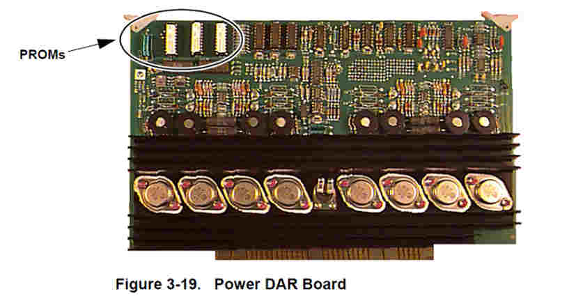
Power DAR Board
gsi laser
Power DAR Boards The two DAR (Digital-to-Analog Resolver) boards plug into a pair of unique slots (X-DAR/A1 and Y-DAR/A2). These slots receive their control signals from the corresponding TS277 step-and-repeat table driver cards in the B1 and B2 slots beneath them. The DAR boards convert a pulse train into appropriately phased currents that drive the forcer along a selected platen axis. The X-DAR board drives the x-axis, while the Y-DAR board drives the y-axis (see Figure 3.4). Each DAR board performs the following functions: • Generates four phase-related stepped sine wave currents that drive the coils for one forcer axis. Provides correction for the x-y cumulative error.
Provides a dampening circuit which reduces the amount of the x-y motor rocking as the forcer decelerates. It does this by sensing back voltage in non-energized motor coils, and converts them to signals delivered to the drivers for the energized coils. This produces an opposing force to any oscillation or ringing of the forcer on the platen. • Provides a ’wash’ circuit which is used to minimize the effects of hysteresis from the x-y motor coils. • Reduces coil current to minimize heat on platen (in some systems). The power DAR boards contain special PROMs which are used to correct for mechanical tolerance variation between the forcer and platen. The PROMs describe the unique manufacturing differences specific to a given forcer’s field coil windings. These PROMs must remain within the system using that forcer! The location of these PROMs is indicated in Figure 3-19. Note: If the boards are replaced, the PROMs must stay with the system as originally supplied. The DAR boards receive their inputs from the TS277 x and y controller cards located in the slots directly below (B1, B2). Input connections are through the backplane. These drive the forcer through the 20-pin I/O connector (J30), and the Z-stage through the 20-pin I/O connector (J10). Connector J11 is also connected to the forcer, though it is used principally for initialization purposes. All power for the forcer and Z-stage is derived through J30 and J10.
In order to minimize the time required to perform maintenance or repairs on your system, it is advisable to maintain a local supply of spare parts.
The quantity and nature of these spare parts is determined by the Periodic Maintenance requirements of the system, and by the number of systems that are installed at your location.
It may also be important to consider the difficulty of shipping components to your location. Spare parts can be ordered either through Specialized Electronic Services. Toll free phone numbers are available. Call Now!
You can also email inquiries regarding the availability of spare parts can be addressed to:
Note: When ordering parts such as galvanometers, lasers or expensive optics, consult SES before you consult other vendors. SES has years of experience and will give you the best pricing and service in the industry.
SES – CALL NOW TOLL FREE: 1-800-681-7374